Sponsored by:

WEBINAR EXECUTIVE SUMMARY
Arc Flash Codes & Compliance:
How to Deliver Protection & Performance
KEY TAKEAWAYS
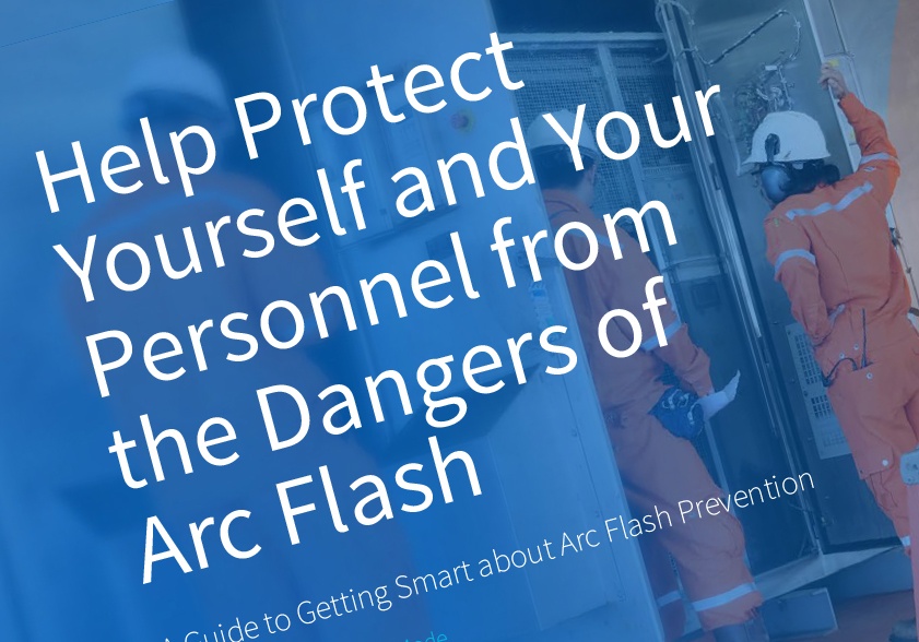
- An arc flash can cause serious injury or death to anyone in its path.
- The National Electrical Code provides installation standards to promote electrical safety and mitigate arc flash risk.
- The right arc flash mitigation solution depends on a business’ needs.
- There are six key levels of hazard risk control to consider when evaluating arc flash mitigation solutions.
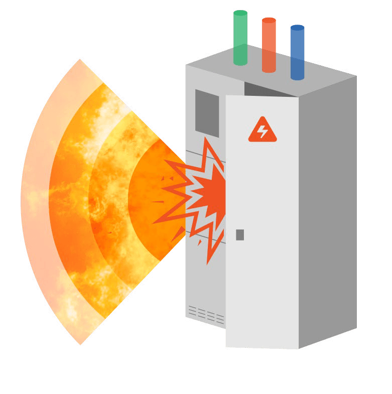
An arc flash event is defined by the National Fire Protection Association (NFPA) as an electrical equipment hazard that is the source of possible injury or damage to health associated with the release of energy caused by an electric arc.
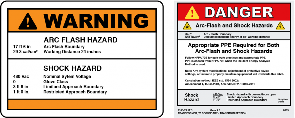
The NFPA’s National Electrical Code (NEC), along with NFPA 70E: Standard for Electrical Safety in the Workplace, provides safety standards that can decrease the impact of an arc flash event. Businesses can take advantage of several technologies and product-based solutions to deliver protection while ensuring they meet their organization’s performance needs.
In our recent webinar, Randy Barnett provided an overview of arc flashes and the NEC articles that focus on providing arc flash safety. Tim Ford discussed the hierarchy of hazard control along with key arc flash mitigation solutions business’s can consider to protect their operators. You can read an executive summary of the webinar below as well as watch the webinar and download a PDF of the summary.


Randy Barnett
NFPA Certified Electrical Professional


Tim Ford
Global Product Manager, ABB
ARC FLASH WEBINAR
Click play to watch the webinar and learn about changes and trends in the latest arc flash-related codes / standards and how these changes impact system design, labeling and PPE requirements.
The severity of an arc flash injury is driven by three key factors that
impact the amount of incident energy released:
impact the amount of incident energy released:

Available fault current delivered at a particular point in the distribution system.
The available fault current is fixed based on what the transformer can deliver, other than changes to the transformer, this is will be a known entity.

Length of time the arcing current lasts, which is limited by overcurrent protective devices like circuit breakers and fuses.
You can change the time that the energy flows. Any effort to reduce the time energy flows means a less likely occurrence of incident energy.

Distance from the operator to the arc.
Determine the safe distance between the operator and the task plane where an arc may occur to limit the amount of energy exposure. Remote tracking devices and chicken switches are two options that add distance between the worker and the equipment. In some situations, the personnel can be moved so they
aren’t in the path of the arc.
aren’t in the path of the arc.
“If a person is burned in an arc flash incident, the odds are they’re going to be severely burned, if not become a fatality.”
– Randy Barnett, NFPA Certified Electrical Professional
The National Electrical Code provides installation standards to promote electrical safety and mitigate arc flash risk.
Arc flash safety standards first appeared in the 2002 National Electrical Code from the National Fire Protection Association. Updated every three years, the 2017 edition of the NEC includes changes that further protect operators from arc flashes. We’ve highlighted some of these changes below.
240.87 Technologies for Reducing Arc Energy
-
Zone-selective interlocking (ZSI)
-
Differential relaying
-
Energy-reducing maintenance switch
-
Energy-reducing active arc flash mitigation system
-
Instantaneous trip setting less than the available arcing current
-
Instantaneous override less than the available arcing current
-
Approved equivalent means; approved by an authority with jurisdiction
240.67 Arc Energy Reduction
Applies where fuses rated 1200 A or higher are installed
Becomes effective January 1, 2020
Becomes effective January 1, 2020
Fuse must have a clearing time of 0.07 seconds or less at the available arcing current, or provide one of:
-
Differential relaying
-
Energy-reducing maintenance switching with local status indicator
-
Energy-reducing active flash mitigation system
-
An approved equivalant means
The right arc flash mitigation solution depends on a business’ needs.
A variety of product-based solutions are available for arc flash mitigation. It is important for businesses to have a thorough understanding of their specific situation and know the details of the equipment and system when choosing the optimal solution. A study is often conducted to assess the potential risk and severity of an arc flash incident.

“Mitigation requires system knowledge, not necessarily expensive solutions.”
– Tim Ford, Global Product Manager, ABB
Product-based solutions all fall within the NFPA 70E’s six levels of the hierarchy of control, ranging from most effective to least effective: Products solve the arc flash problem by containing, limiting, or preventing the event, and can provide protection either full-time or part-time.
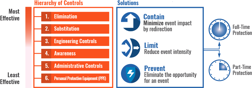
There are six key levels of hazard risk control to consider when evaluating arc flash mitigation solutions. Some solutions are listed below with the associated hazard risk control level identified.
1. Arc Resistant Gear
- Hierarchy Level 3: Engineering Control
- Contains by redirecting energy away from the operator through a plenum
- Protection is available only when the equipment doors are closed, which is done manually
 ADVANTAGES
- Operator protection as long as the door is closed
- Widely available
- Visible
- Easy to understand
 DISADVANTAGES
- Isolated but substantial equipment damage
- No operator protection if the door is open
- High implementation costs
- Equipment downtime/replacement
- Rated energy can be exceeded in the incoming compartment
2. Energy-Reducing Maintenance Switch
- Hierarchy Level 5: Administrative Control
- Limits by reducing the event intensity via a circuit breaker tripping response
- Part-time protection; requires manual activation to turn switch on as the default setting is off for optimized uptime and reliability
 ADVANTAGES
- Operator protection when on
- Widely available simple solution
- Minimized nuisance tripping and equipment damage
- Cost effective
- Visual indication of on/off state
 DISADVANTAGES
- Manual operation; requires human intervention to turn on
- Higher safety and uptime risk
3. ZSI
- Hierarchy Level 3: Engineering Control
- Arbitrates protection delays in preference of improved (faster) protection without negatively impacting selectivity
- Maintains faster protection even if wiring fails or is cut
- Simple, commonly available and cost effective to implement
 ADVANTAGES
- Uptime and reliability with fast protection and good selective coordination
- No human intervention required
- Possible to retrofit to existing products
- Reduced incident energy, which changes the energy ratings on the label, reducing PPE needs
- Threshold-ZSI available in some cases
 DISADVANTAGES
- Requires coordination study
- Requires maintenance
4. Active Arc Flash Mitigation Systems
- Hierarchy Level 3: Engineering Control, or Level 5: Administrative Control, depending on implementation
- Contains by redirecting energy away from the operator to an internal containment zone
- Part-time (administrative control) or full-time (engineering control) protection set via switch
 ADVANTAGES
- Operator protection when active, even when the door is open
- Minimizes equipment damage
- Diagnostics and test capabilities
- Reduces incident energy to minimum
- Changes the energy ratings on the label when protection is set for full-time, reducing PPE needs
 DISADVANTAGES
- Expensive add-on
- Larger footprint for retrofit and new systems
- Not widely offered
5. PtD
- Hierarchy Level 2: Substitution
- Prevents by reducing the opportunity for a bus fault event via non-conductive coating
- Full-time protection; factory-installed non-conductive coating is always on
 ADVANTAGES
- Reduces probability of an event
- Operator protection across most of the system
- Prevents unwanted downtime
- Widely available
 DISADVANTAGES
- Not available systemwide; not all buses can be coated
- Cannot retrofit
- Expensive
- Doesn’t satisfy the NEC; code compliance needs to be addressed separately
6. Lock Out/Tag Out
- Hierarchy Level 5: Administrative Control
- Electrically safe condition: personnel do not work on live equipment
- Prevents; nearly removes the possibility of an arc flash occurrence, although some risk remains during the de-energization phase
- Protection requires manual operator intervention to de-energize the equipment
 ADVANTAGES
- Best solution, most efficient
- No specific
- Cost-effective
 DISADVANTAGES
- Requires human intervention, and is therefore subject to human error
- Cost prohibitive if using full redundancy to create the electrically safe condition
NFPA 70E is the standard for electrical safety in the workplace.
It is not a law, but OSHA can enforce it through the general duty clause. Because it is also an approved consensus standard, it holds up in a court of law.
